
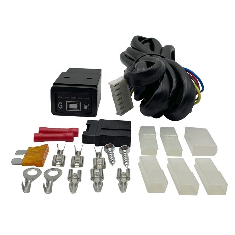
725 GNV CNG LPG Fuel Changeover Switch
The 725 switch provides fuel-selection functions in compatible autogas installations. Confirm the exact version, wiring diagram and supported control arrangement before ordering. Do not assume compatibility with every mixer or sequential injection system.
Compatibility depends on electrical connections and control logic. Check whether the installation requires direct actuator control or communication with a specific ECU. Similar appearance does not establish interchangeability.
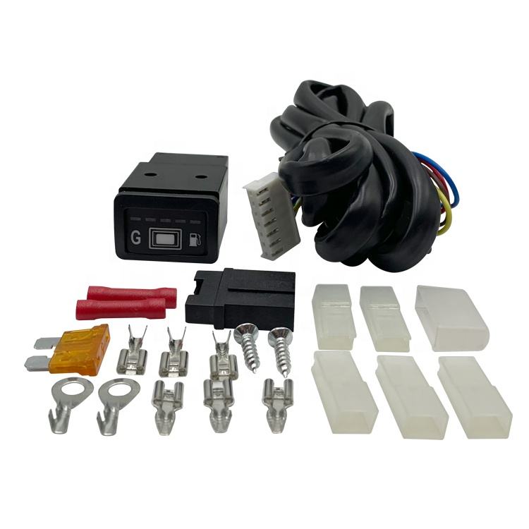
Product Parameters
The following values are listed in the product information. Confirm their definitions and test conditions for the supplied switch.
| Model | 725 |
|---|---|
| Function | Fuel selection in a compatible CNG or LPG system |
| Listed Supply Voltage | 10–15 V DC |
| Listed Current Without Solenoid Load | <500 mA; confirm operating state and measurement conditions |
| Listed Maximum Drive Output | 3 A; confirm whether per channel or total, continuous or peak, and the permitted load type |
| Listed Operating Temperature | −10°C to +85°C; confirm installation and test conditions |
| Connections | Request connector details, pin assignment and wiring diagram |
Will It Match Your ECU and Actuators?
The system design determines whether this switch is suitable. Provide the ECU, existing switch and actuator details for review. A reducer model alone does not establish electrical compatibility.
Controller: ECU model and required switch interface.
Wiring: Supply, ground, input and output connections.
Actuators: Coil voltage, running current and startup current.
Output arrangement: Number of channels, permitted loads and switching sequence.
Operating logic: Required fuel-selection and engine-stop behavior.
Mixer and sequential injection systems may use different control arrangements. Review the conversion kit component guide when checking the complete installation.
What Must Be Confirmed About the 3 A Output?
A maximum current value needs a defined rating basis. Request whether 3 A applies to one output or all outputs together. Confirm continuous and transient limits before connecting actuators.
Rated supply voltage and ambient temperature
Continuous and peak current limits
Permitted inductive loads and protection requirements
Channel-sharing or simultaneous-load restrictions
Specified wiring and circuit-protection requirements
Do not assume every solenoid is compatible. Compare the actuator specifications with the documented output limits and installation instructions.
What Switching Functions Should Buyers Verify?
Fuel switching follows the supported system logic. Confirm the operating sequence instead of assuming instantaneous changeover or identical behavior across installations.
Supported fuel-selection modes
Required engine-running or other control inputs
Actuator activation and deactivation sequence
Any supported delay and its adjustment method
Indicators or warnings provided by the supplied version
Specified behavior when the engine stops or an input is lost
The switch should not be presented as a complete system safeguard. Confirm its role alongside the ECU, valves and other controls in the documented configuration.
Which Inspection Records Should You Request?
Functional records should identify the tested version and acceptance criteria. Request applicable evidence for the switch in your order.
Supply testing: Operating behavior under stated voltage conditions.
Output testing: Load type, current, duration and measured result.
Switching testing: Input conditions, sequence and response criteria.
Temperature testing: Operating state and test profile supporting the listed range.
Traceability: Product reference, batch and inspection date.
Product documents must match the supplied switch. Review our certification information and request applicable reports where required.
Frequently Asked Questions
Does the 725 switch fit every CNG or LPG conversion?
No universal compatibility is established by this listing. Confirm ECU interface, wiring, actuator loads and operating logic before selection.
Can it work with an AT09 reducer?
The reducer name alone is insufficient. Identify the electrical valve or actuator being controlled, its ratings and the complete control arrangement. Confirm compatibility against the wiring diagram.
What should be checked if switching is delayed or unresponsive?
Several electrical or configuration issues can cause these symptoms. Qualified technicians should check supply voltage, grounding, wiring, required inputs, actuator loads and supported operating logic before replacing the switch.
Can it replace an existing fuel selector directly?
Replacement requires connection and function checks. Compare pin assignments, output type, load ratings and control sequence. A matching plug does not prove compatibility.
Where should the switch be installed?
Use the mounting location specified in the installation instructions. Respect the listed temperature range and applicable limits for moisture, vibration and exposure. Do not assume an unlisted enclosure protection rating.
Is professional installation required?
Qualified autogas technicians should complete wiring and commissioning. Follow the switch instructions and applicable local requirements. Verify supported functions before service.
Are bulk orders or customized labels available?
Order and customization requirements can be reviewed with the quotation. Specify quantity, labeling, packaging and destination. Confirm feasibility, minimum order quantity and lead time.
Request a 725 Changeover Switch Quotation
Send the existing switch and system details for a compatibility review. Include ECU model, connector photographs, wiring information, actuator ratings and required quantity.
Confirm supply scope before ordering. Request the exact version, harness or connector inclusion, wiring diagram, price, warranty and delivery lead time.